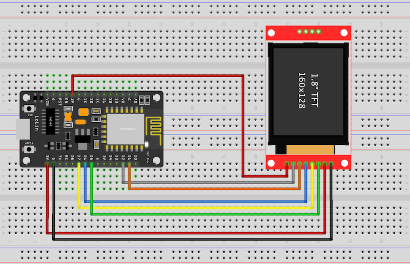
Few months ago I've ordered this 1.77" TFT LCD screen. Display is ST7735S compatible, but the issue I was having is how to correctly wire up the display to an ESP8266 board (NodeMCU ESP-12E), since the markings on the board were not consistent with other diagrams for using the SPI interface of ESP8266 on the internet.
After some trial and error I managed to figure it out.
| TFT PIN# | TFT PIN marking | NodeMCU PIN# | ESP pin |
|---|---|---|---|
| 1 | GND | G | GND |
| 2 | VCC | 3V | 3.3V |
| 3 | SCK | D5 | GPIO14 (HSCLK) |
| 4 | SDA | D7 | GPIO13 (HMOSI) |
| 5 | RES | D6 | GPIO12 (HMISO) |
| 6 | RS | D1 | GPIO5 |
| 7 | CS | D2 | GPIO4 |
| 8 | LEDA | 3V | 3.3V |
Hardware SPI pins (CLK, MOSI, MISO) are fixed, others you can choose freely (the ones connected to RS and CS of the display).
The 8th pin is providing power to the backlight LED so it can be connected to some other PIN if you want to be able to dimm the display.

With these connections in place, the correct way to initalize the ST7735S library is like this:
#include <Adafruit_GFX.h>    // Core graphics library
#include <Adafruit_ST7735.h> // Hardware-specific library for ST7735
#include <SPI.h>

#define TFT_CS         4
#define TFT_RST        16
#define TFT_DC         5

#define COLOR1 ST7735_WHITE
#define COLOR2 ST7735_BLACK

Adafruit_ST7735 tft = Adafruit_ST7735(TFT_CS, TFT_DC, TFT_RST);

void setup(void) {
  Serial.begin(115200);

  tft.initR(INITR_BLACKTAB);      // Init ST7735S chip, black tab
  tft.fillScreen(COLOR2);

  // Let's draw a small table
  tft.drawRect(0, 0, tft.width(), tft.height(), COLOR1);
  tft.drawLine(0, 50, tft.width(), 50, COLOR1);
  tft.drawLine(0, 100, tft.width(), 100, COLOR1);
}
Comments